
Note #1: The following section describes how existing parabolic troughs operate, their design and market limitations, including desalination. The most common current application is electrical generation. Currently there are over 100,000 parabolic troughs operating in dozens of solar fields worldwide generating electricity. While there are wide variations in size, markets and efficiencies, the existing trough design described here is the most common manufactured by dozens of companies worldwide primarily for electrical generation and is therefore used for comparison to the Ringtrough.
Note #2: Desalination is not discussed until later sections because the existing trough described here cannot be used efficiently and affordably for desalination. This section does describe why existing troughs are not suitable for heating seawater efficiently and are therefore not being widely used for that purpose. The Ringtrough is therefore more of a new technology than a disruptive one since it is creating new markets for trough technology.
Note #3: The information contained here is written primarily for engineers but in a manner which non-engineers can understand. This represents 10 years of self-education in the still emerging field of concentrated solar power. I encourage everyone reading this to perform their own research on each statement made here.
We at JennSolar are absolutely certain that the Ringtrough will contribute significantly to the world’s energy and water needs.
Parabolic Troughs
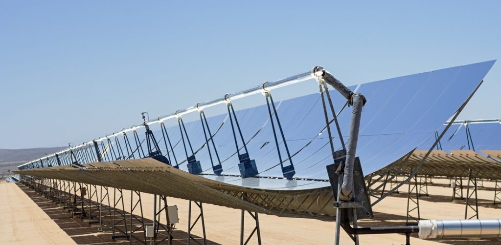
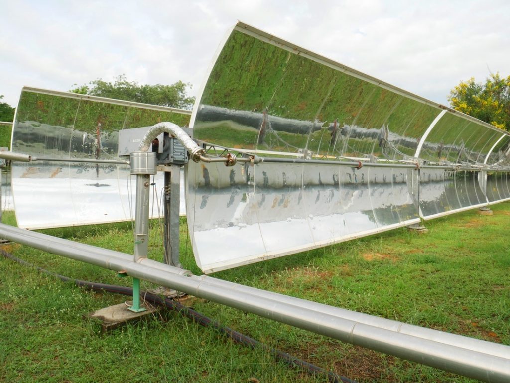
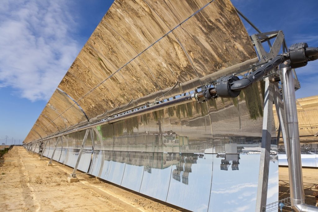
All satellite dishes are a parabola, because a parabola is the only geometric shape which allows the radiation hitting the dish to be reflected and magnified onto a single focal point. If the satellite dish were cut in half and that parabolic cross section made into a trough, then the sunlight would reflect onto a focal line running down the center of the trough instead of a focal point. If a 70mm (3)” pipe called a collector tube, is placed in the focal line of a 6.77m (23’) wide parabolic trough mirror, then the sunlight is reflected and magnified 80 times, heating up the thermal fluid in the tube. The thermal fluid is then piped to a heat exchanger to extract the heat and is returned to the solar field to be reheated. This is one of the most efficient types of concentrated solar power and is used worldwide by dozens of manufacturers to generate renewable energy.
However, the current trough design has significant limitations. Existing troughs have the collector tube attached to and support by the trough, located about 2m (6’) away from the rotation line. This results in the collector tube rotating through a semi-circle with a 4m (12’) diameter as the trough slowly rotates to follow the sun throughout the day. This is the largest limitation on existing trough systems which the Ringtrough eliminates.
Flexible Joints
The collector tube slowly moves throughout the day in a semi-circle with a diameter of 4 m (12′). Each end of the line of collector tubes is connected to a non-moving manifold system, which delivers the thermal fluid into one end of the collector tube and collects the heated fluid at the far end of the line of troughs into another manifold. The piping connection from the line of troughs to the manifold must therefore be a flexible connection consisting of either rotating joints or flexible piping.
These flexible joints represent the weakest mechanical link in the thermal fluid piping system, with each flexible joint having an upper pressure limit, beyond which the joint becomes more expensive, joint movement more difficult, and the risk of failure increases. The flexible joints necessitate the use of synthetic oil as the thermal medium. Since fluids do not expand when heated, a synthetic oil system only subjects the flexible joints to the operating pressure head associated with moving the synthetic oil through the collector system via pumps.
Synthetic Oil System
Tens of thousands of gallons of costly and flammable synthetic oil are required to operate a typical existing large solar array. The synthetic oil system includes a reservoir and pumps to circulate the oil through the solar array to a heat-exchanger system, where the thermal energy in the oil is used to generate steam for use in the steam turbine.
Oil to Steam Heat Transfer Losses
The synthetic oil is heated by the solar array to 400°C (750°F). However, the synthetic oil then needs to convert that heat into superheated steam that can then be sent through a steam turbine to produce electricity. This is accomplished in separate heat transfer equipment where the energy collected in the solar field is used to manufacture steam. The loss of efficiency associated with the heat transfer from oil to steam is 15%.
Synthetic Oil Temperature Limit
The optimum operating temperature for a typical steam turbine generating electricity is 540°C (1000°F) superheated steam. Therefore, synthetic oil with a maximum operating temperature of 400°C (750°F) generates superheated steam at a temperature lower than required for optimum turbine efficiency. Most existing solar fields boost the final steam temperature and pressure with natural gas to reach the optimum temperature and pressure for electrical generation. This adds equipment and operating costs.
Synthetic Oil Decomposition
Current synthetic oils have an upper temperature limit of 400°C (750°F), beyond which synthetic oil decomposition accelerates. Even at the designed 400°C (750°F) operating temperatures, synthetic oil decomposes. This imposes a material life cycle limit after which the oil is either recycled or replaced, adding to the operating costs for the solar field.
Trough Rotation
Existing parabolic trough mirrors have a range of movement limited by the mechanisms, which control them, and the collector tube flexible joints. Each mirror is currently limited to about 200° of circular movement, enough to follow the sun and to tilt the mirrors slightly downward for maintenance and cleaning. The troughs cannot be inverted completely, which is beneficial to avoid blowing wind and dust accumulation. Likewise, existing troughs cannot be easily protected during inclement weather, such as high winds blowing sand and dust against the mirrors.
Trough Aperture Size Limit
Existing parabolic mirrors require a very rigid structure (space frame) to support them. Each manufacturer has their own combination of mirror material and space frame, but they all exhibit the same general relationship of mirror to structure. The space frame extends out from a strong central axis around which the trough pivots. The loads exerted on this center structure include the dead load of the trough, plus the live load of the wind acting on the mirror. The central axis is subjected to the torsional loads (twisting) imposed by the wind acting on the mirror. These wind loads are like the wind acting on the sail of a boat; the greater the wind speed, the greater the sailboat heels over, and the greater the force that is transmitted down the sailboat’s mast to the boat’s structure.
The wind blows on the mirror creating torque along the center axis. The center axis must resist this torque, or allow the mirror to be moved by the wind. Since the sunlight is being reflected from a 6.77 m (23′) wide mirror onto a 70 mm (3″) diameter collector tube, the mirror must be held rigidly in place, or the mirror will lose focus. At the same time, mechanical equipment moves the mirror very slowly and precisely to follow the sun, and maintain the focus on the focal line.
It is the maximum designed wind loading that determines the strength of the space frame and therefore the amount of material required to build it. This cost benefit analysis keeps current mirror apertures at a maximum of 6.77 m (23′). Beyond this aperture distance, the structural cost increases do not justify the heat gain increases.
Benefits of Greater Aperture Size
The amount of sunlight reflected onto a collector tube is determined by how wide (aperture) the trough is. The wider the trough, the more sunlight gets reflected onto the same length of collector tube. A wider trough delivering more sunlight onto the collector tube will have a heat gain equal to the increase in aperture size. This translates into efficiencies and cost savings.
Parabolic Troughs for Desalination
Desalination and renewable energy have not been efficiently combined yet on a large scale. In a world of decreasing fossil fuels and increasing desalination, a new way must be created which uses renewable energy. The Ringtrough will desalinate using 100% renewable energy.